MuTag
| Project: MuTag | |
|---|---|

| |
| Status | Finished |
| Participants | Mrmoddom |
| Last Update | 2025-05-07 |
MuTag v2.1
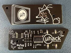
The first MuHack's NFC keychain!
This is a custom PCB with the ATTiny44a microcontroller and an ST25 NFC ISO15 tag.
From the microcontroller, you can access the NFC tag via I²C, modify its configuration, and read/write data.
Features
- MCU: ATTiny44a
- NFC Tag: ST25 NFC ISO15 (4 Kbit memory)
- Energy harvesting
- High-speed Mailbox: 256 bytes
- 4 LEDs in different colors
- Dimensions: 20 × 60 mm
Getting Started
In the Hardware folder, you'll find the PCB design files and electrical schematics.
#define YELLOW_LED 0
#define GREEN_LED  1
#define BLUE_LED   2
#define RED_LED    3
The LEDs are connected to:
- Yellow → PA0
- Green → PA1
- Blue → PA2
- Red → PA3
The NFC tag is on the I²C bus of the ATTiny:
- SDA → PA6
- SCL → PA4
The tag's GPO pin is connected to INT0 of the ATTiny (PB2).
Activating Energy Harvesting Mode
By default, the tag is in "on demand" mode. To set it to permanent energy harvesting mode:
- Install the ST25 NFC app from the Play Store: https://play.google.com/store/apps/details?id=com.st.st25nfc
- Scan the tag and go to "Register Management"
- Read the tag again; locate the register `EH_MODE` (0x01 = on demand)
- Set `EH_MODE` to 0x00 and press "Save" (default password = 0000)
Programming the ATTiny44a
An external ISP programmer is required: we will use an Arduino Uno as the programmer.
- Upload the `ArduinoISP` sketch to the Arduino.
- Add this URL to the "Additional Boards Manager URLs" in the Arduino IDE preferences:
http://drazzy.com/package_drazzy.com_index.json
- Install "ATTinyCore" by Spence Konde and select:
| Option | Value |
|---|---|
| Board | ATTiny24/44/84 (noBootloader) |
| Chip | ATTiny44(a) (v2.0 → select 24) |
| Clock | 1 MHz internal |
| BOD | Disabled |
| LTO | Enabled |
| EEPROM | Retained |
| millis()/micros() | Enabled |
| Programmer | Arduino as ISP |
- MuTag ↔ Arduino connections:
| MuTag | Arduino |
|---|---|
| VDD | 5 V |
| GND | GND |
| SCK | 13 |
| MISO | 12 |
| MOSI | 11 |
| RST | 10 |
- Note:* The through-hole pads on the MuTag are now 2.54 mm.
To start flashing, touch GND with the Arduino's reset pin a few seconds before hitting "Upload" in the IDE (or use "Upload using Programmer").
Accessing the NFC tag via I²C
The internal memory of the ST25 tag is mapped as an I²C EEPROM at address `0x53`. Example sketch: `Hello_MuHack.ino`.
TODO
- Add 3D model of the PCB
- Find a bootloader for UART programming
- Evaluate removing the diodes
- Enlarge programming pads
- Change MCU to ATTiny44/84 (more memory)
- Remove the `RESET` pad
Bootloader Notes
The Optiboot bootloader (Spence Konde) uses the AIN0/AIN1 pins (connected to the LEDs). Options:
- Remove the LEDs to use the pins for UART
- Recompile the bootloader with different pins
This project is designed as a keychain (single programming), so the LEDs were kept and the bootloader was not invested in.
License
Copyright © 2023 MrMoDDoM This project is licensed under the GNU Affero General Public License (AGPL-3.0). See LICENSE.md for details.
Links
- Project page on GitHub: https://github.com/MrMoDDoM/MuTag
- Google Play ST25 NFC App: https://play.google.com/store/apps/details?id=com.st.st25nfc